Hi all,
so there have been several requests to Tangent about a version of the Element panels, that have illuminated buttons.
To my understanding, it is just not cost-effective to put in LEDs to illuminate the buttons properly. It would simply make the panel more expensive by quite a lot.
So Tangent decided, that the grey buttons on the darker fascia are contrasty enough and else, a little light next to the panel will do the job much cheaper, than integrating a whole heap of LEDs into the panels.
So for those, who are still looking into adding some lights to their Element panels and don’t want to use fluorescent window color – here’s what I did.
Be aware that as soon as you open up your panels, your warranty is void and I will not be responsible for any damage done to the panels throughout our little workshop here.
So what do we need:
– a T10 Torx screwdriver
– pencil and ruler
– some white diffusion, or just plain white paper
– some mirror foil (optionally)
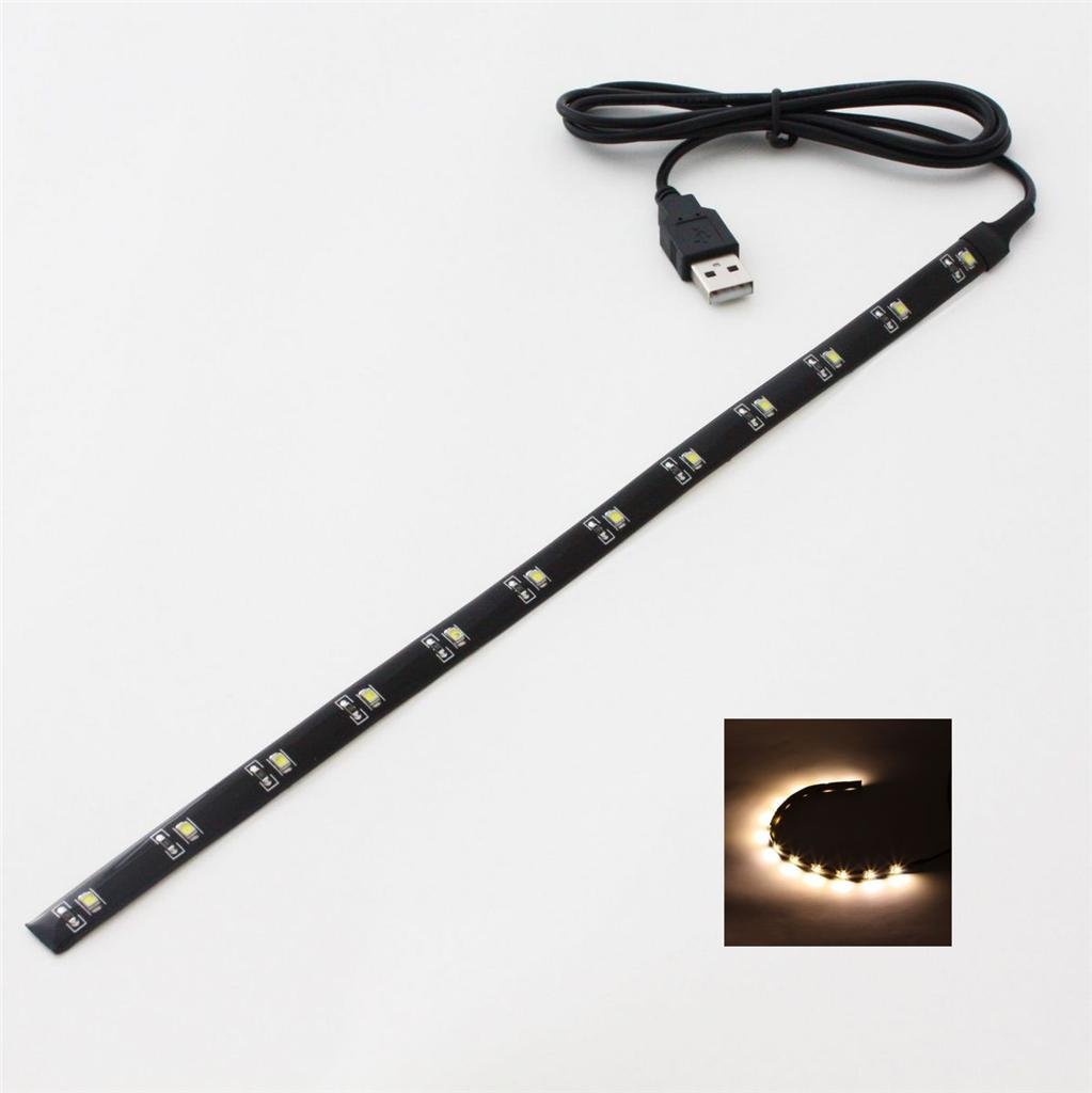
– 8 LED flexbands from Amazon (roughly 6 USD / € per piece)
1) Lets take the panel apart!
So we need to disassemble the whole thing, before we can put our stuff in.
First, there are 4 screws – 2 on each side – to remove the silver stand of each panel. Be careful – as soon as you remove the stand, the little magnets come falling out. Make sure not to lose them.
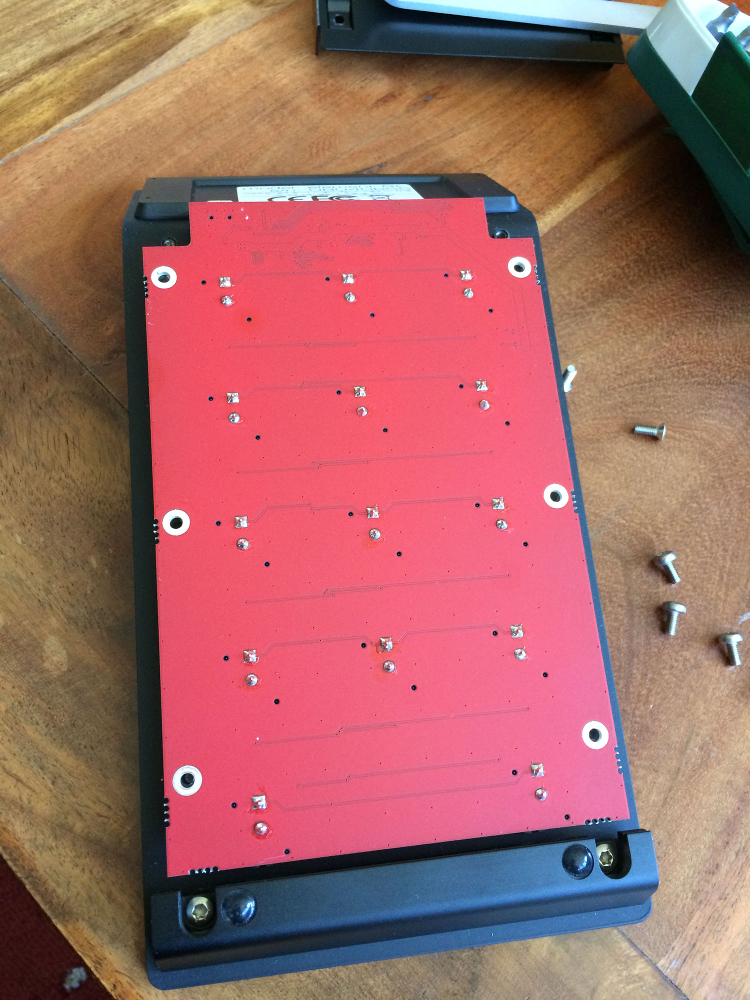
Next, the bottom plate needs to be unscrewed with 2 screws and the remaining 4 screws on the red controller board beneath.
Again, be careful when grabbing the red controller board – it is still attached to the display with a small (and short) flatband cable!
To losen the cable, you need to unlock the socket it sits in, on the controller board.
It’s pretty easy to lift the little lid of the socket – use a creditcard or something else that does not hurt the board in case you slip.
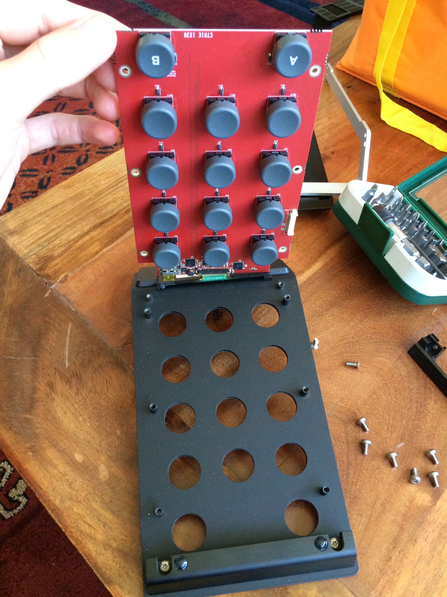
Then carefully remove the red controller board.
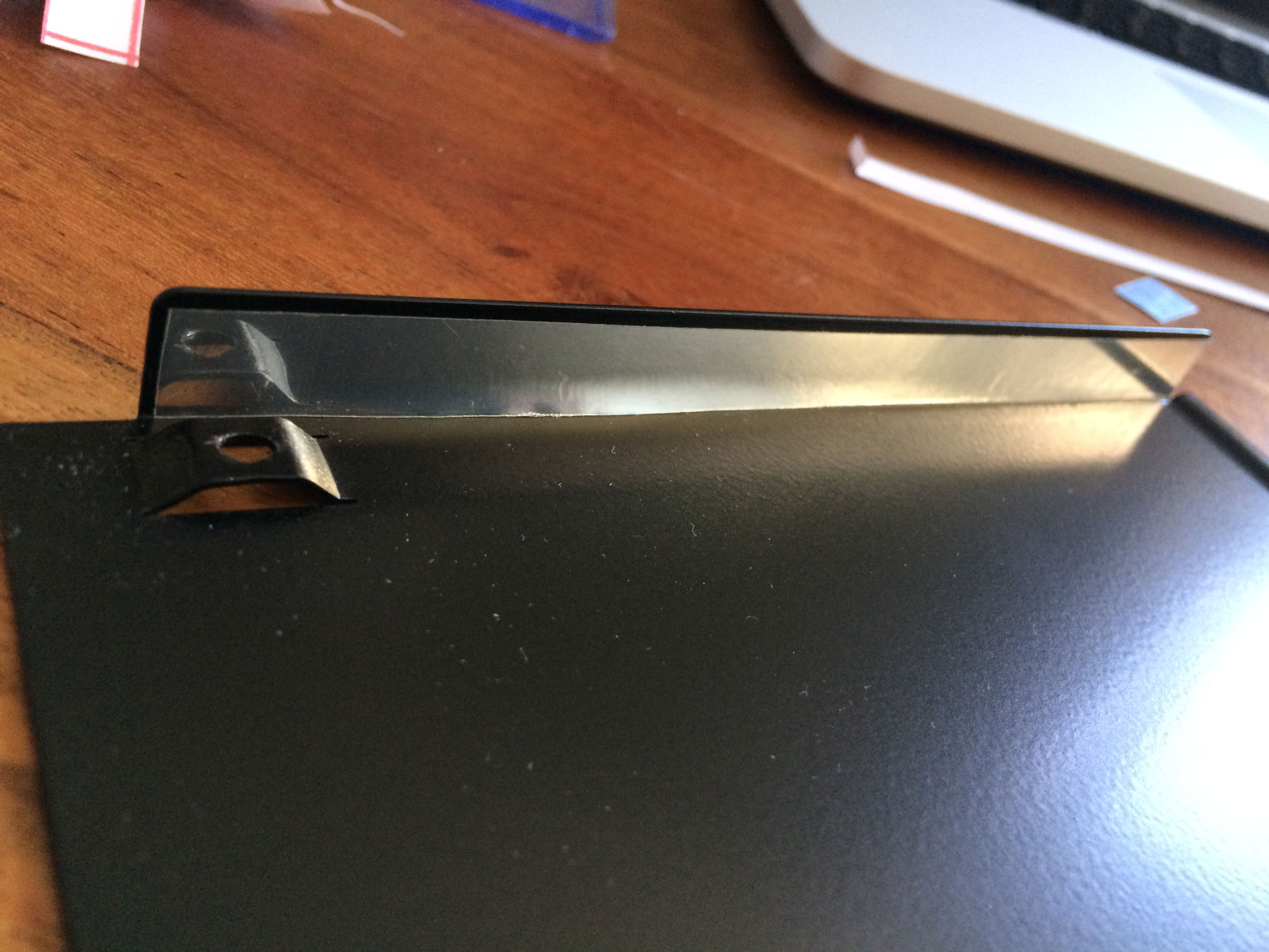
Lastly, you need to remove the little metal piece on the back, where the USB-connector of the controller board goes through, with two more screws.
2) Prepare the ingredients
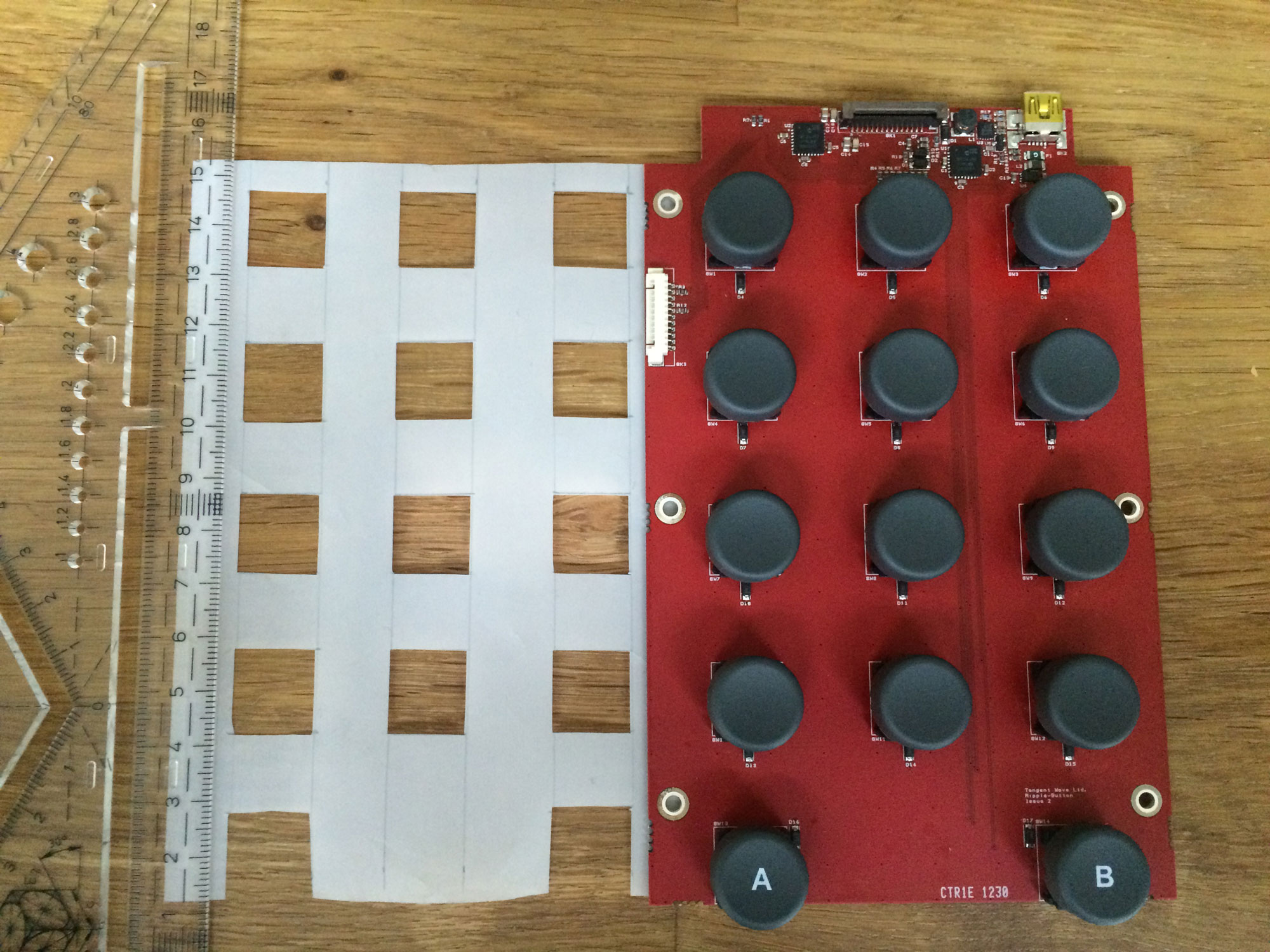
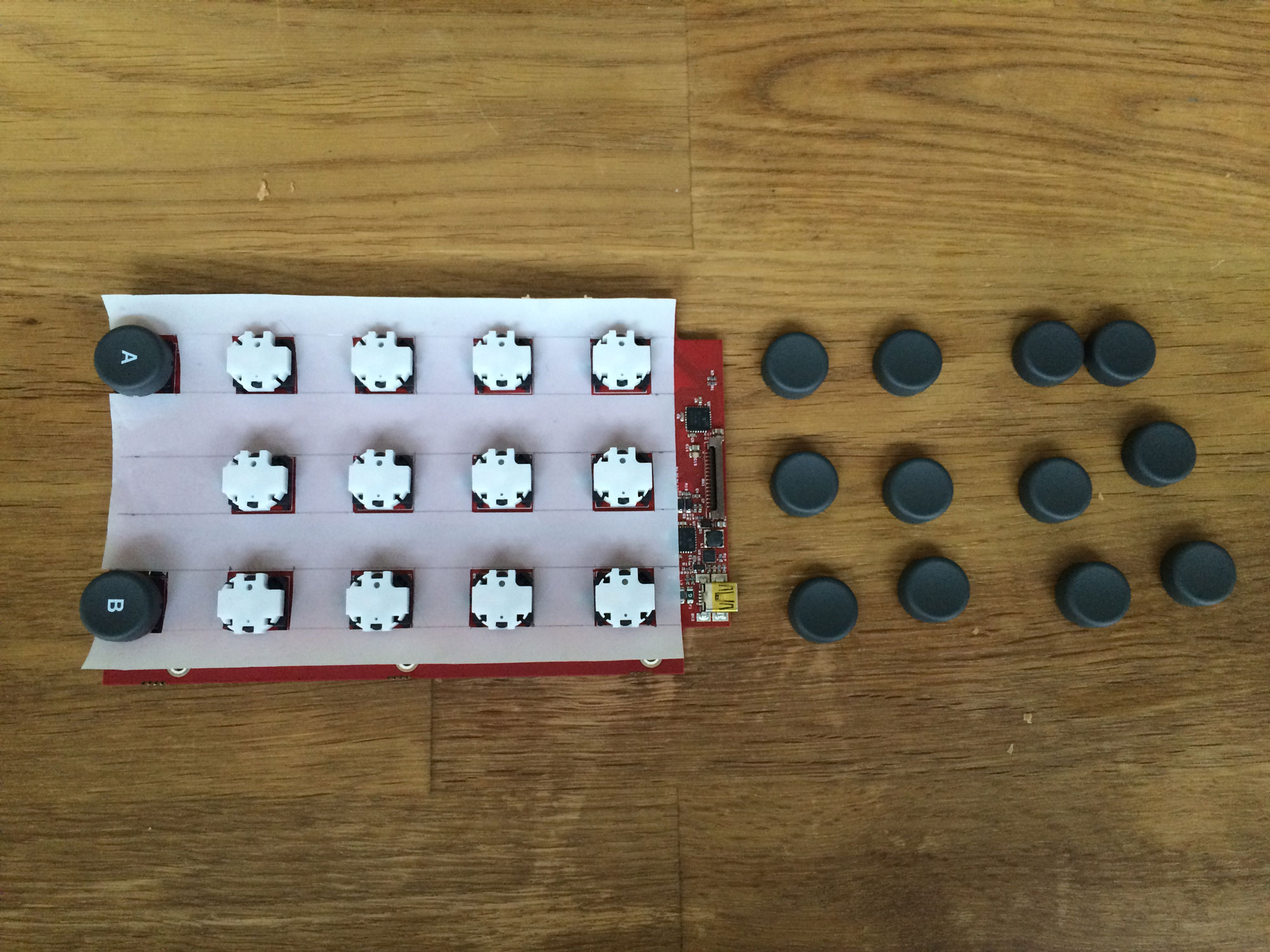
Now comes the fiddly part: Take the ruler and measure all the buttons, distances, etc. in order to cut the wholes for the buttons into the white diffusion. Once done, remove the button caps from the controller board (you can just pull them off) and put the white diffusion in place.
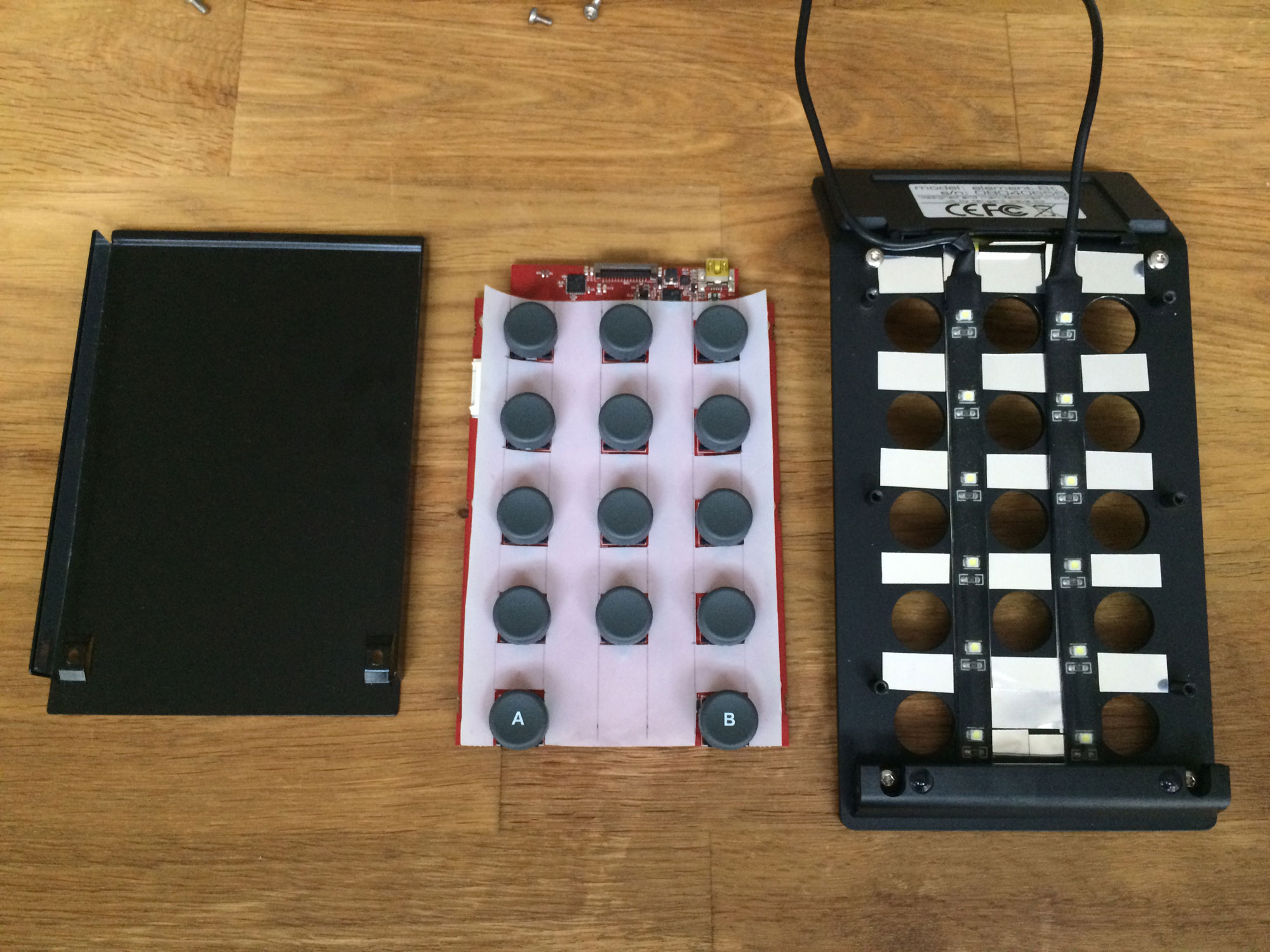
After that, put the button caps back on. Next, cut the USB LED-strips to proper length as shown in the picture. Then stick them to the back of the top-plate – they come self-adhesive, so no need for glue or anything.
This way they now light towards the bottom onto the white diffusion, that is supposed to smoothly spread the light.
In the picture, you can see some mirrorfoil left and right to the LED strips – this actually was from an earlier try with mirror foil all over, but I found mirror foil reflecting the pure LEDs through the slits around the buttons and blending my eyes. So mirror foil instead of white diffusion is a no-go 🙂 .
Lastly, put two thin strips of mirror foil to the left and right „walls“ of the bottom plate to reflect any light going there back into the panel.
As we have only two LED-strips in the middle rows of the panel, the outside button rows will need some light – that’s what those mirror foil strips are for.
The effect actually is not super-big, but noticeable.


3) Put everything back together
So now we have our pieces here and need to put them back together again. First, re-attach the flatband cable for the display and make sure it sits correctly in it’s socket. Then be careful when screwing the red controller board back in: Make sure the two USB-cables from the LED strips are not
in the way – there is a small inductor between the flatband cable and the USB connector, that might get hurt by the cable,
as it ends right where that inductor sits – make sure to guide the cable around. Then put the bottom cover plate back on and also the silver stands with their magnets.
Note, that because we removed the metal-piece in the back, now you can only screw the stands with two screws and magnets.
See picture below on how it should look in the end and what parts remain.
Of course feel free to drill holes for the two new cables into the metal piece, so you can put that back in as well.
However, I just left it out for the time being.
Now rinse and repreat with all other panels – the Tk panel might just need one LED-strip from left to right over all buttons, whereas the Mf panel might need 3 to illuminate all buttons halfway equally.
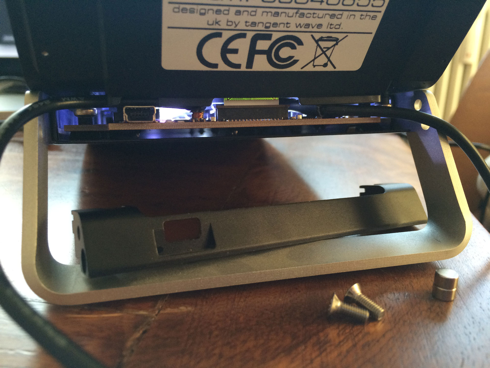
Anyhow – here’s the result from our Bt panel here:
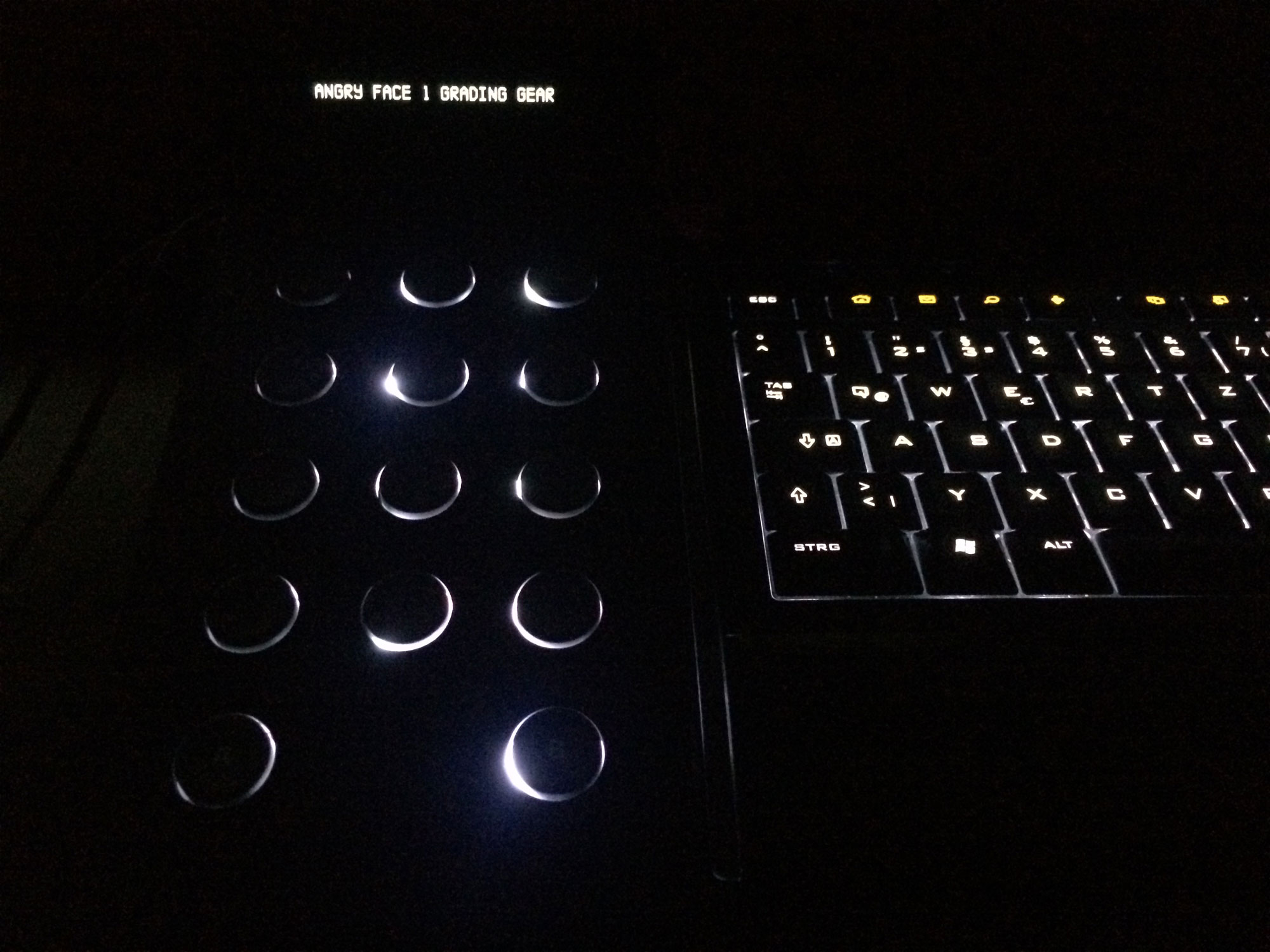

It looks a bit blending, but in fact this is more my crappy cell phone camera not doing a good job. It works pretty well this way and does not disturb the eyes. Let me know, if you have other ideas on how to illuminate your Element panels! Meanwhilst, I hope this gives you an idea about how and how difficult this is to achieve and what it looks like in the end.
Now imagine this inside a Rageboard 🙂 .
Cheers,
Mazze